Tuesday, 18 March 2014

Day Thirteen

Yesterday I was musing on this disc thing at bottom right. I don't know what it is but there are three of them on the top deck. I doctored them and was thinking to leave them as they are. 
But I was looking through my tool collection and I found this - it's actually for tagging animals' ears. And it cuts out perfect circles that are exactly the right size to reproduce that disc thingie. Winner!
 
This hatch on the right will be open for the range-finder. All the photos I have say there are no hooks on the outside of this pair of hatches (strange, one would have thought). You can see there's no external hook because of the way the hatch is sitting. But I will enjoy modelling that lozenge-shaped latch there on the inside and maybe I will want to do the hinges.

See, no hook. I don't get it. The hatch next to it has a hook. How was it opened from the outside - pocketknife? Big magnet?
I have a visitor.

Going to build this latch. It's a loop of steel welded to a little block.
Styrene rod .5mm. I am bending this around a steel point and there is also a bit of tweezer action.
1.5mm styrene beam
Pretty certain by now that the styrene glue I'm using either is not working, or I have two or more radically different types of styrene. I use Araldite for this one. When it's dry I'll file it clean up the excess glue very carefully as I suspect styrene is one of the few things that epoxy does not bond so well with.
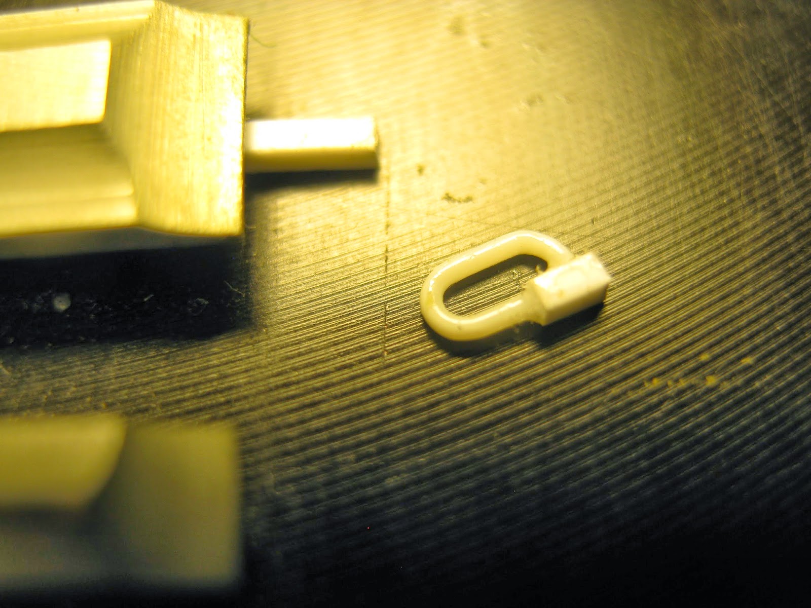
But the part is a little too big. Silly me. This loop scaled up would be 17.5mm diameter in section. I'll try it with the .3mm copper rod (made by the Lion Roar company). .3 x 35 = 10.5mm.

Day Twelve


To warm up something easy, that I can't mess up. I affix the wire for the night light. I have photos showing the wire coming out of the light but none showing where it goes to. I have photos of the wire running up the big weld line between glacis and side armour - but not telling me where the wire ends. Luckily, the book has this drawing. Great; now I know Point A and Point B. I do not attempt to model this as per the possibly fanciful drawing as the wire casing is a flexible job and they would have made it as short as possible.

Looks about right to me.
Now we have a bit of cleaning up to do. The original guard I made for the gunner's periscope is rubbish, I pull it off and have another go.
Much better, and with little holes in it too. I improve the little pin sticking out on the left. I drill, I mount a bit of styrene rod on something flat and glue that from behind. It looks messy but I'll be cleaning up things like this before I paint. In the photo I espy a round cap thing which on the kit is like a socket; I'd been wondering about that. I need a little disc of plastic or steel.
I hack it off and there we go. Too easy. I might just leave this as it; no one will know. I did drill out the periscope. Photo shows me what a poor job I did. I will scrape that clean with a brand new blade.
Look what I found in my spares box. An MG34 barrel by Armorscale. Makes me feel I might work on the machine gun mounting.
So here are the bits. The kit parts are fairly good. The kit parts at far left have ejector pin marks. But Academy has done very well to minimise these, and seams on this kit - practically non-existent. The precision is awesome 10/10. I was thinking of finding an after-market gun but the beautiful brass barrel and shield will get this over the line. Notice I have NOT used nippers to free these parts from the sprue. Nippers will break delicate parts.

Instead, I use one of these saw attachments on my dremel; this goes through the plastic like a knife through butter. Some parts you can hack out with a knife, some parts you really can't. For delicate parts you need one of these.
Book has PLENTY of detail. It's highly likely the brass barrel I'm going to use is not exactly the right one but meh who cares.


Hmmmmm. Okay, I will build with what I have. I will glue the gun to the mount with Aquadhere and not fix the whole assembly permanently. That means I can always get an after-market set and replace it sometime in the future. I'll get back to you when I have it all together.


This is the peg for where the butt stock is removed. I won't even both trying to clean this part up, I'll replace it with a bit of styrene rod.
The brass barrel is going to cost me; I'll have to make a sight and work out all those other bits. At least I have good photos. The cooling sheath (is that what it is?) is getting drilled out until it's super-thin.


I manage all this without too much difficulty.


But I do not manage this. I have spent two hours trying to glue these shields on. I had one on perfectly but in trying to fit the other I broke it off. About ten times now I have messed it up and had to use the debonder to clean up. I'll keep at it.


That was one of the worst modelling experiences I've ever had. Four hours I think. The shields are holding on by a thread. They were not bent perfectly and that's probably why they didn't join properly. They will break off at the slightest touch. And I see I forgot to file the rear end of the shield, those two little tags from where I cut them out. Right. I am out of options. I put a few little blobs of Araldite inside to fortify the construction; I have to because I still have a fair bit of work to do on this assembly. By now I just don't care. Into every life a little rain must fall. At least the shields are all squared up and that's the important thing. We'll pull it all together somehow. I'm going to make a ham cheese tomato toastie and watch Family Guy. Enough for one day. Man.

Next time - I've been thinking about this - I will buy two of the kit and two of the brass. It makes sense, it really does: second chance with every part you tackle OR best of two every time.

Hmm. The Araldite has set and the damage isn't too bad, and I'm feeling a little better. There was one thing I wanted to attend to today, a quick job. At the sides and on the top of the gun mantlet are holes which house what I learn from my book are centering bolts -
- which in the kit are only hinted at with these three divets.
So I drill them. To smooth the edges of the holes I twiddle my pointy blade in there very, very gently.

Sunday, 16 March 2014

Day Eleven

The wooden block that goes with the jack is, happily for me, an ugly affair.


I find a bit of beech - can't locate the maple. I sand it to size and chisel little rebates for the metal straps. I don't do a very precise job but in this case that is okay because the thing I am trying to model is not precise either. I've got the grain of the wood the wrong way but there's no turning back now. Anyway, you've seen the brass etched part; it was hopeless and the kit part was a joke (sorry Academy, you dropped the ball on that one). This jack block is better than either of them so I'm going to sign off on it.I guess that's the difference between modelling armour and modelling planes; with armour you can make a bit of mess, fudge things here and there, hide your mistakes under accessories or mud. With planes you can't do that; everything has to be spot on. I haven't made a plane since I was a child; maybe I should.

I'm getting dangerously close to painting time. I have only to add some brackets, which I will cunningly leave open (I can't put the tools in them and hope to paint them well in situ) such that I can put the painted tools in and close them when I've got the vehicle base coat on.

I have to put on many, many hooks, the smallest hooks I have ever attempted. Because they are so delicate I'll do those last of all otherwise I'll probably keep breaking them off while I am working. There are a few other little bits and pieces. I can use these and get an acceptable result but really what I need to do is build a jig and bend them out of copper rod. We shall see.


This is what they really look like. I have to get them in the right places, straight, and in line, and I don't fancy my chances.


Let's make the brackets for the jack. In fact, let's make all the remaining tool brackets and get them out of the way.

Here is the photo.


Here are the kit parts. I've looked through my book and I see no evidence at all for a folding handle. If there were, this handle would be too long and too thin. I'm going to shear it away but keep the pin. To make the new handle I'll mount a bit of aluminium tubing on my Dremel and try to put a tiny bit of a barrel effect on it. I'll be able to stick a pin in the end.

For the brackets, here are the brass parts and their instructions. Scary. That H thing is the kit part.


Noice. I'm getting better at this folding business.


Now let's see about that not-fold-away handle -_-

Chop!
Comes away easily with just two cuts - good old chisel blade.

Clean it up and make a handle from stretched sprue, which I drill so I can mount it easily and cleanly.
Now stretch some more sprue, this time fairly fine.
This is how you make bolts - by holding the end of the sprue up to the candle. Or at least it's how you make A bolt because good luck to you getting two the same. Luckily I only need one of these things -

- to put on the end of the handle. But the handle seems to me now to be a tad long. So I cut it off where it meets the crank and remount it -
- on the wrong side of the crank. Bugger it.
All better. I won't mount the handle just yet, I want the jack in the brackets first so I can rest the handle against the hull as per the photograph.
And then I enter into a nightmare realm, and there I dwell for many hours.  I tried to fit the jack mounts, and the latch for the sledgehammer. The brass instructions are approximate in their indication of exactly where to place these things. There is some variation in the photos I have. I could not make the jack mounts relate to the sledgehammer mounts, and nor could I see where the stay for the skirt was supposed to fit in. I made a distressing superglue mess. So I took the Track guard off completely. I used superglue debonder to dissolve and remove all the errant superglue. I stood the jack mounts in two more little ponds of the stuff and they are still there; hopefully in a moment when I pick them up I will be able to wipe the glue off their feet. Then, I put the track guard back on and fit just that one skirt, whose stay/strut I will need to work around. This will become my reference point because at least I can be fairly sure where it goes. Now I think I have a clearer idea of where to place the other bits. The two little holes in the hull are for the kit crowbar fixtures. This is clearly incompatible with the shovel mount (as provided). In many of the photos I have, there is no shovel and no shovel mount. I will remove the shovel mount. I'll tuck the shovel in somewhere, as I please.

I put the crowbar mounts in place. I see that bit of glue under the top bracket - don't worry, it's gone.

I can't bear to leave things in a state and now I'm back on square one and feeling a little better. And so to bed.

Day Ten

Last night I tried to attach four little pegs to a flat bracket, as you saw. This morning I went to try and clean it up and at the very first touch it fell apart. Maybe this styrene glue of mine is old, has gone off. This part is, so far, the hardest thing I have tried to do. We are talking about sticking four bits of rod to something. Ach. Put it in the too-hard basket just for now. There has to be a way, I just haven't thought of it yet. No good working on something that is upsetting me. 


So I'll get on with something else. Early on we looked at the muffler. Here is that picture again to remind us of what we are trying to achieve.


I thought this might be difficult but really all I have to do is saw a piece of aluminium tube at the right angle, and I have no trouble with that. Any mess just gets filed away. Before I saw it I ream out the end of the smaller part with my knife as it will be harder to do once I cut the part free.The other section is long enough that I won't have any handling problem.

There's the first attempt. I got pretty close but the angle wasn't quite right. It's joined with superglue.
So I have another go. And another. This one is a keeper. Sixth attempt.


I have to say, I consider this an improvement.


I'll keep this plastic part, the exhaust pipe itself. I need to do a few things though. I need to drill out the business end - easy-peasy. But where the exhaust pipe goes into the flame damper (that's what that big elbowy thing is - it was to hide any sparks or flames at nighttime) we have what looks like a nightmare. That disc on the exhaust pipe has to come off and so does the little collar. 

I don't know if you have Milo where you are - chocky drink. It comes with this steel foil seal, very useful stuff. I got this one out with the minimum of crumpling. I will try to make those fins inside with this material. The little hose-clamp part doesn't bother me, that will be fairly easy, but those fins/braces look hard.
Speaking of drilling, these are pin-vices. I have quite the collection as you can see but I use this aluminium one by Proedge pretty much exclusively because it is so light, meaning it is less likely to break the finer drill bits.


I want this yet thinner but we are in the danger zone; The plastic is starting to whiten under the stress and if I push it the rim will break. Still I have options. I can move the drill about a bit, angle it. And I can put the point of my knife in there and twiddle it ever so gently with the only force being the weight of the knife itself. With a blunt blade, not a sharp one.


Okay, we have been trying all sorts of things. As you can see, I tried to bend up the braces with the thin sheet steel. I am not doing too well, as you can see. But then, a stroke of genius! I decide that before I can put these details on I really need to put the plastic exhaust pipe and the metal cover together. There on the right, that's a cigarette filter, and it sleeves snugly inside the elbow joint. All I have to do is cut off a bit of it, poke the exhaust pipe through the middle, and slide the whole thing inside the damper. Then, when I've got everything perfectly lined up, I can inject diluted Aquadhere into the filter and it should set fairly firm. Now the whole thing will be stable enough for me to apply the last remaining details. Do I dare to put that dent in it? Knowing I could so easily break it? I guess I can do a trial with one of the earlier attempts. 

This is what I mean. I will fill those ejector pin marks, don't want anyone looking up my muffler and finding something wrong.
This cigarette filter was such a good idea. And on that high note let me bid you good night XD